API Overview
One of the ways in which we have tried to create a good experience for new developers is by using standard ROS interfaces. This means that code you might have written for other robots in the past should be easily portable to your new robot.
Whenever possible, we have conformed to the ROS Enhancement Proposals (REPs). These documents provide the foundation of standard ROS interfaces.
Fork and Reach
The fork and reach of the robot are controlled by an interface defined in robot_mechanism_controllers/JointPositionController
Publishing a float to the /minireach/fork_position_controller/command topic will make the controller try to move the linear motor that controls the fork to an extension defined by the float in meters. For the moment, height 0.0 is calibrated to mean that the underside of the forks are touching the ground and can not go any lower. The top of the forks will end up at about 1 cm (thickness of the forks) above the published height because of this.
The reach joint can be controlled in a similar manner by publishing to /minireach/reach_position_controller/command.
Only one controller is allowed to control a joint at a time.
Base Interface
Support for mobile bases is quite standard and robust in ROS, however it is one of the older interfaces. As such, it is one of the few interfaces which is not action-based.
The mobile base subscribes to base_controller/command, and accepts a geometry_msgs/Twist message.
Only two fields are used in the message:
linear.xspecifies the robot’s forward velocityangular.zspecifies the robot’s turning velocity
User applications will typically not connect directly to base_controller/command, but rather to cmd_vel or nav_vel. A multiplexer is always running between teleop_vel and cmd_vel and a few other topics. Whenever the deadman on the robot controller is held, teleop_vel will override cmd_vel. The advantage of having your application publish to nav_vel rather than directly to base_controller/command is that you can override bad commands by simply pressing the deadman on the robot controller.
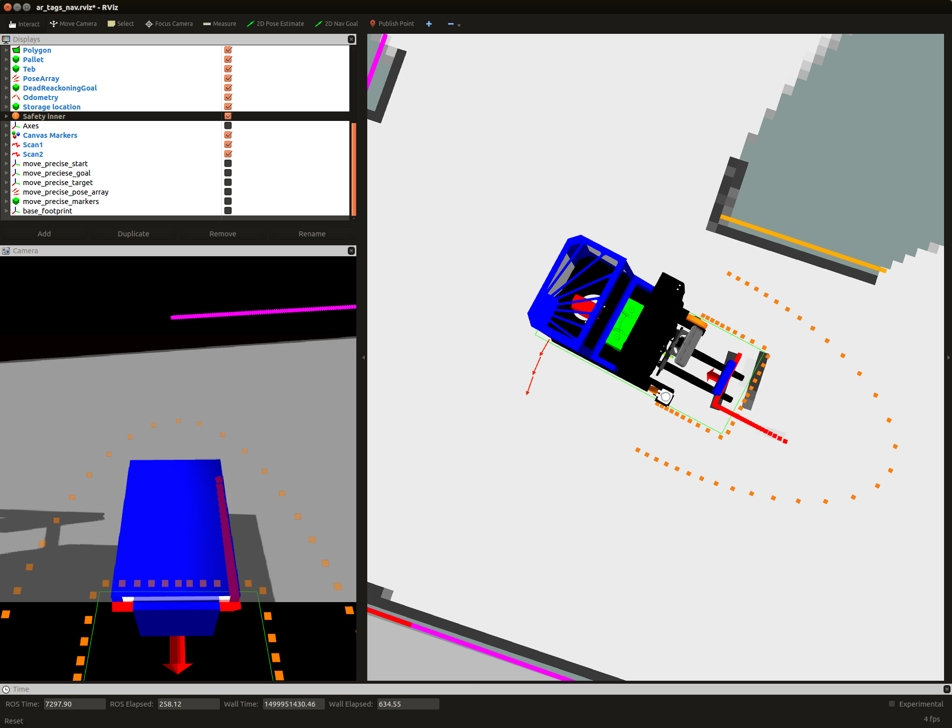
The truck has support for speed reduction when in the proximity of obstacles. When this system is active, the truck will not be able to drive into obstacles that are detected by the laser scanners. Is will also limit the maximum allowed speed close to obstacles. This prevents the truck from picking upp pallets, so it has to be deactivated during pallet handling.
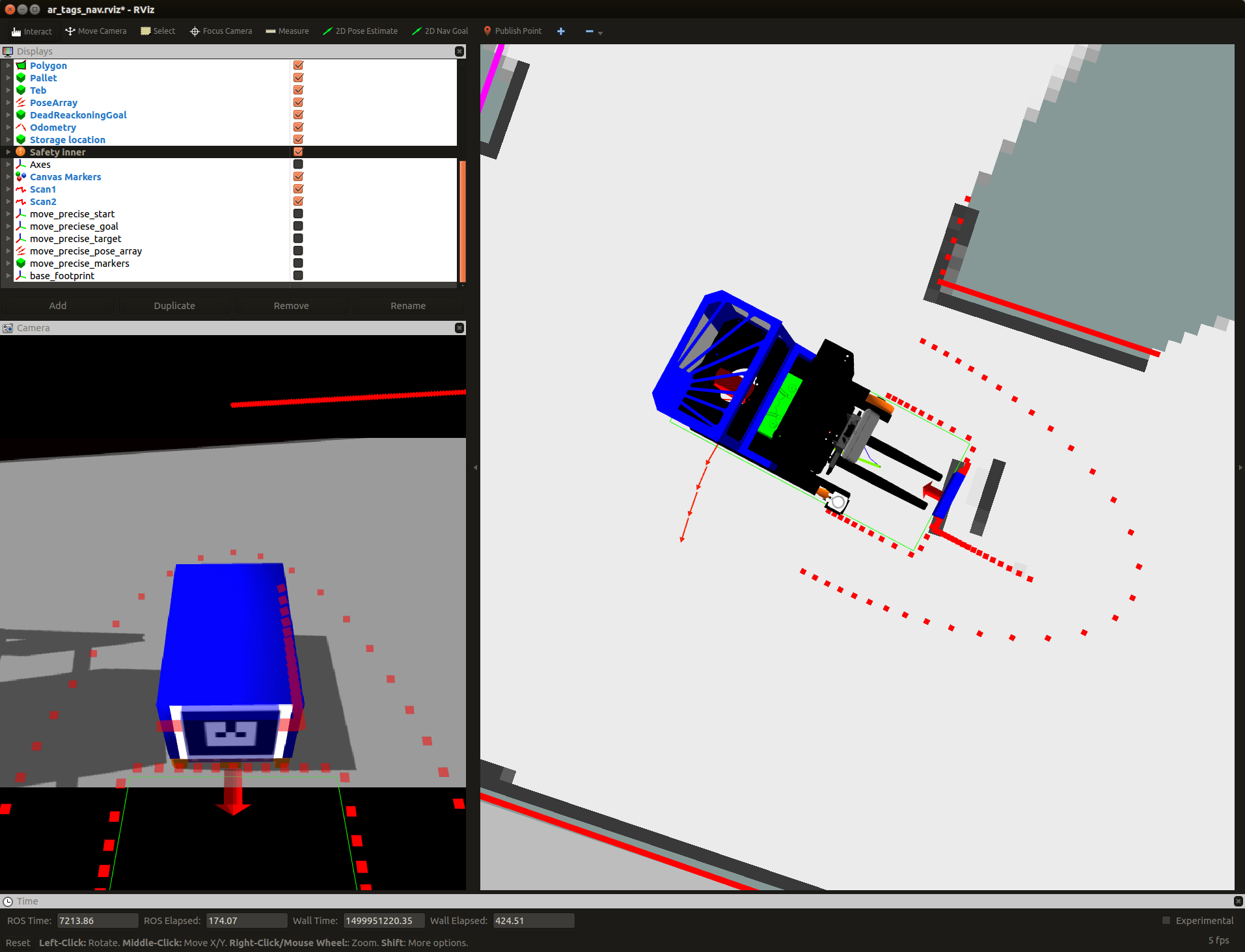
The visualization of the safety fields turns red when some obstacle (red arrow) is in the stop field (red rectangle). This completly stops the truck from moving in that direction.
This terminal command diables safety as long as it is running:
rostopic pub -r 10 /disable_safety std_msgs/String "data: ''"
3D Camera Tilt Interface
The 3D camera in the fork facing direction on the robot is controlled by an interface defined in robot_mechanism_controllers/JointPositionController
Publishing a float to the /minireach/camera_tilt_controller/command topic will make the controller try to move the camera tilt axis to the angle defined by the value of that float in radians.
rostopic pub /camera_tilt_controller/command std_msgs/Float6"data: 0.8"
3D Camera Interface
We have been avaluating two different 3D cameras for the MiniReach, the ZED stereo camera and the structured light based (kinect like) Orbbec Astra.
The following infromation is for the Orbbec Astra.
The fork facing camera exposes several topics of interest:
- camera/depth_registered/points is a sensor_msgs/PointCloud2 which has both 3d and color data. It is published at VGA resolution (640x480) at 30Hz.
- camera/rgb/image_raw is a sensor_msgs/Image. This is just the 2d unrectified color data. It is published at VGA resolution (640x480)
- camera/rgb/image_rect_color is a sensor_msgs/Image. This is the rectified 2d color data. In simulation this topic is a slightly delayed copy of camera/rgb/image_raw. On the real truck this It is published at VGA resolution (640x480) at 3330Hz.
Laser Interface
scan1 is a sensor_msgs/LaserScan from the fork laser. scan2 is a sensor_msgs/LaserScan from the drive_wheel laser. scan is a merged version of scan1 and scan2 on the base footprint frame. (used by SLAM algoritm)