Robot Hardware Overview
Mechanism Terminology
The MiniReach kinematics are defined by using the concepts of joints, links, and coordinate frames. The robot URDF (unified robot description format) model specifies the attributes (kinematic tree, names, ranges, etc.) of the joints, links, and frames of the truck. A link element in the URDF describes a rigid body with inertia, visual features, and coordinate frames. A joint element in the URDF defines the kinematics, dynamics, safety limits, and type (revolute, continuous fixed, prismatic, floating, or planar). Fixed joints are typically used to describe the relationship between two rigidly joined components in the truck.
Link
The links are defined in the URDF description that are located in the minireach_description package.
Frame
Frames represent the coordinate frames of links, detected objects, sensors, or the location of another truck in the world. Frames are defined relative to other frames and the transformations between each frame is tracked using TF. See http://wiki.ros.org/tf for more information.
Joint
A joint describes the relationship between links and are defined in the URDF description that can be found in the minireach_description package. The drive and steer joints are rotational, the fork and reach joint are prismatic, and there are several fixed joints describing the location of sensors on the truck. Rotational and translational joints are represented similarly in the URDF, and joint forces are described as effort instead of force or torque. Position, and velocity are both used to describe linear and angular motion of a joint.
Coordinate System
The coordinate frames for most links are defined with positive z-axis up, positive x-axis in drive wheel direction and positive y-axis to the truck-left when facing drive wheel direction.
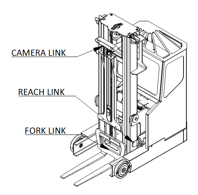
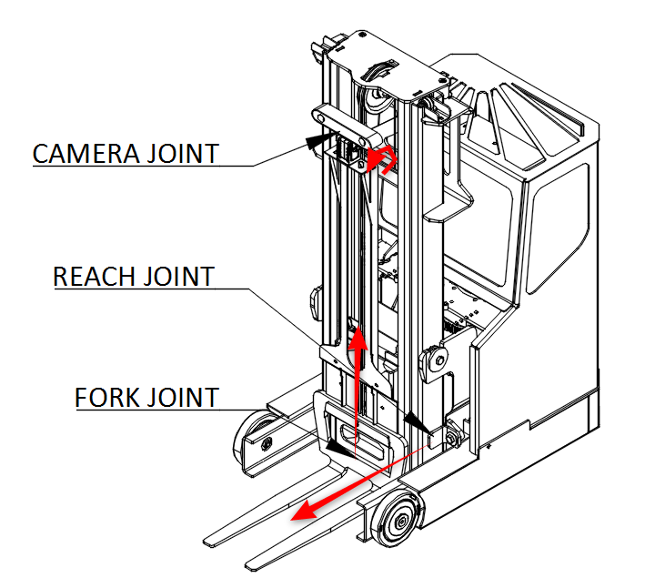
Naming Conventions
In general, the names for a link, a joint, and frame will be similar (e.g. fork_link, fork_joint, and fork_frame). The diagrams below show the link and joint naming conventions as well as the positive direction of joint motion.
Mechanical Overview
Do not operate MiniReach before reviewing the mechanical information listed below.
Environmental
The MiniReach trucks are indoor laboratory robots. Operating outside this type of environment could cause damage to the MiniReach trucks, and injury or death to operators.
Drive Surface
- The drive surface of the robot must be capable of supporting the entire weight of MiniReach, about 180 kgs plus the weight of the payload. If the surface is too soft, MiniReach can get stuck and fail to drive. A commercial carpet, tile or cement floor is recommended.
- MiniReach’s ground clearence is only 1.5cm, so make sure the surface is flat enough.
Incline Surface
- MiniReach can be used with ramps, which are at no more than a [1/12?] slope. Ramps that are steeper than a [1/12?] slope are unsafe and may be a tipping hazard.
Water
- MiniReach has not been tested for any type of contact with water or any other liquid. Under no circumstances should MiniReach come in contact with water from rain, mist, ground water (puddles) and any other liquid. Water contact can cause damage to the electrical circuitry and the mechanism.
Forces and Torques
Joint position, velocity, and force limits are implemented in the URDF file as well as in firmware. These joint limits control the range of travel of the mechanism and the allowable velocity to prevent over-travel.
Electrical Overview
Communication Overview
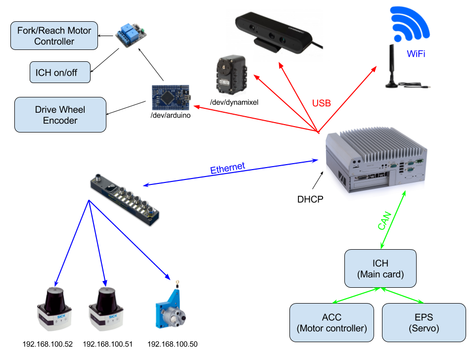
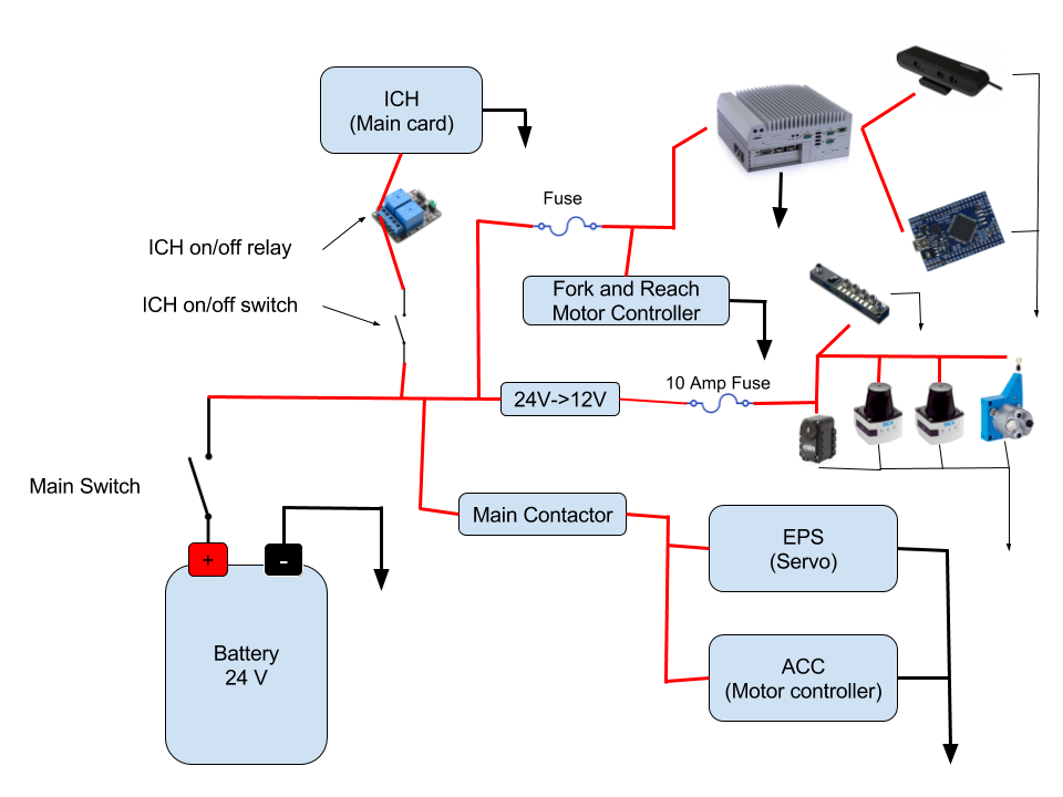
Internally, MiniReach has a number of circuit boards, communication buses, and other components which handle power distribution and motion control. The system comprises among other things:
- The main robot computer (Nuvo-5095GC), running ROS, is responsible for perception and high level control of the robot.
- Ethernet interfaces used to communicate with the scanning laser range finders in the front and back of the robot and the wire encoder for the forks (height).
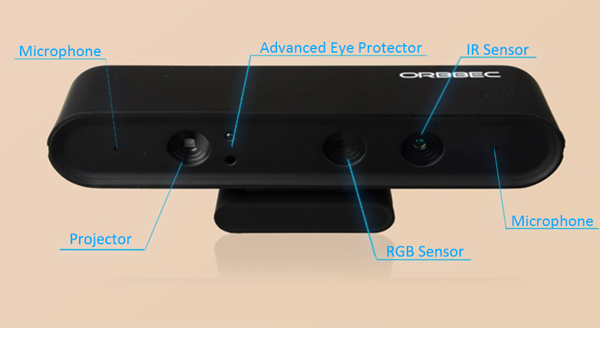
- An Orbbec Astra 3D camera connected by USB.
- A digital servo for tilting the camera connected to the computer by USB-serial port.
- An Arduino connected by USB the computer. It is hooked up to an encoder that outputs ticks from the drive wheel rotation, relay modules that allow control of fork and reach motors and a relay connected in series with the ICH “truck controller” power input.
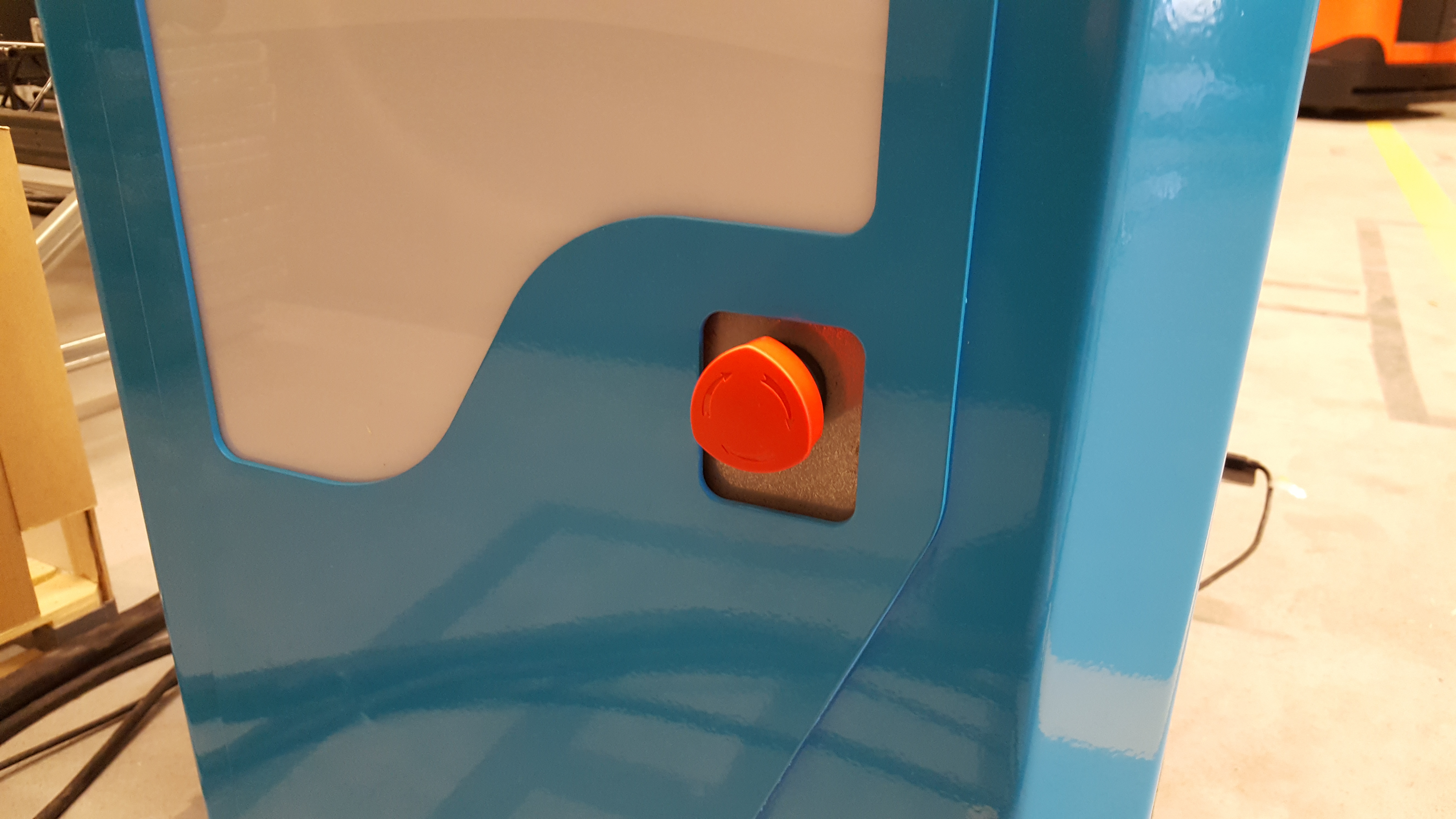
Power Disconnect Switch
The power disconnect is on the right side of the battery. This switch cuts the power between the battery and all systems on the robot.
Emergency Stop
The runstop is used to stop all operation of the base. When the runstop is pressed, the drivers will not be able to communicate with the motor or servo controller boards, and thus the wheel angle and other data will not update in RVIZ.
Arduino
TODO
Arduino:
RX0: TX1: D2: Vit INTERRUPT_WHEEL_ENCODER D3: Ljusblå INTERRUPT_WHEEL_ENCODER D4: D5: D6: D7: D8: D9: D10: Lila LIFT_UP_DOWN D11: Blå REACH_IN_OUT D12: Gul LIFT_ON_OFF D13: Grön REACH_ON_OFF D14: Lila TCS D15: Blå Okänd, Till Relä D16: Gul Oanvänd D17: Grön Oanvänd
Reachkortet (?): IN1 Grön - Från D13 IN2 Gul - Från D12 IN3 Blå - Från D11 IN4 Lila - Från D10
Motion Control
The drive motor and steer servo have dedicated motor controllers connected to the CAN bus. The real-time components of the controls run on these CAN nodes. The main computer streams commands to a third node on the CAN network refered to here as ICH with a frequency of 50Hz using a socketcan interface. The ICH board handles communication with the motor and servo controllers as well as low-level safety, fault protection and diagnostics.
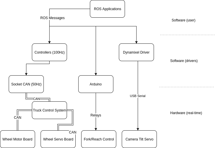
The servo has a position interface and the drive motor a velocity interface.
The servo returns joint position information and motor velocity information.
It should be noted that the velocity information sent by the drive motor is not of sufficient resolution and low enough noise level for odometry calucation, so a separate encoder (not on the CAN bus) is currently used for this.
The motor contoller interface for the fork and reach joints are currently very primitive and can only be used to go up and down without speed control and no feedback.
Sensor Overview
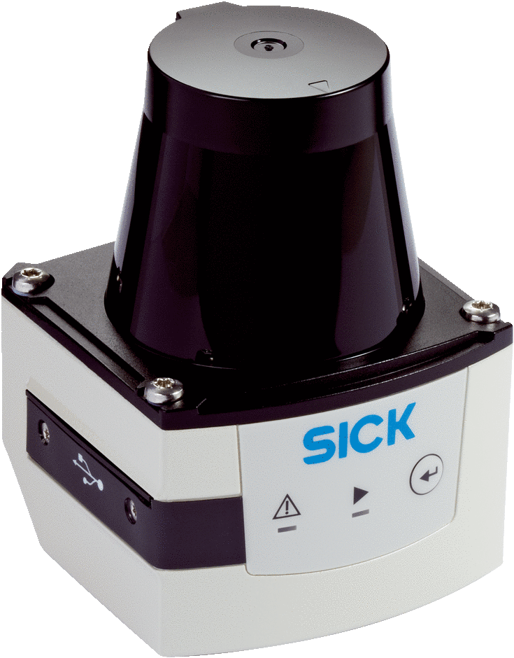
Laser Scanners
The truck has two Sick TiM 561 laser scanners. One mounted in front of the drive wheel and the other on a support leg by the forks. The lasers have a range of 10m, 270° field of view, 15Hz update rate and angular resolution of 0.33°. They publish distances to the scan1 and scan2 topics in ROS.
3D Camera
The truck has an Orbbec Astra 3D camera in the fork direction. This depth camera works best in the 0.4-8m range. See 3D Camera Interface for details on the ROS API.